The content of this page has not been vetted since shifting away from MediaWiki. If you’d like to help, check out the how to help guide!
SpotSpine
This plugin allows to detect and count dendritic spines, to segment spine heads, to trace spine necks, to obtain quantitative morphological measurements.
Spine detection and spine heads segmentation use algorithms from the plugin 3D ImageJ Suite.
Spine necks tracing uses algorithms from the plugin SNT.
Authors
Jean-François Gilles, Thomas Boudier, Tiago Ferreira, Nicolas Heck.
Documentation
First step required before running SpotSpine
Prior using SpotSpine, the dendrite should be traced and the traced model should be saved in swc file format. Several softwares offer to trace dendrites, such as the ImageJ plugin SNT, NeuTube, Neuronstudio, among others. Others formats can be converted in swc.
Before running SpotSpine, place in the same folder the image stack and the .swc file that contains the model of the dendrite. The swc file should be name exactly as the image stack. You can place several image and swc files in the same folder ; SpotSpine will automatically read the image name and find the corresponding swc file.
It is advised to improve the signal to noise ratio of your image stacks. Deconvolution is generally recommanded, but denoising can be enough ; the plugin PureDenoise offers great efficiency.
Using SpotSpine
1. Open the image stack
If not, the image should be calibrated. Go to Image>Properties and give pixel width, pixel height, voxel depth (i.e. z-step of image stack) in microns.
Launch SpotSpine : Plugins>Spot Spine
2. Choose values for spine detection parameters
Spines are detected by spotting their local maxima. A local maxima is a voxel which intensity is higher that the intensities of the neighbouring voxels. The voxel of highest intensity will be detected in each spine head. Still, some parameters need to be adjusted to avoid local maxima in the background, spine necks, or dendrite surface. Note that no maxima can be detected in the volume covered by the dendrite model.
Three parameters can be adjusted, but you will have the possibility to change again these settings in a further step (see Section 4).
-
Threshold intensity Determine that value by estimating the intensity of the spine head that is the less bright in the image. The threshold value means that any maxima which intensity is below that value will not be detected. If the value is too high, some spines will be missing. If the value is too low, some maxima may be detected in the background.
-
Mimimum distance to dendrite and Maximum distance to dendrite
Estimate the minimal and maximal distance from the border of the dendrite. Without a mimimum distance, some maxima may be detected within the dendrite if the swc model does not cover the whole dendritic diameter. With a too high value for the maximum distance, some maxima may be detected in a neighbouring dendrite.
3. Click on Ok to import the dendrite model and detect the spines
The dendrite model is imported in the image (but it is not visible at that step).
No maxima can be detected within the volume occupied by the dendrite model. The detected maxima are displayed in green on the image stack and on the maximum projection.
You can modify the brightness&Contrast (Image>Adjust>Brightness/Contrast), you can zoom in and out (zoom icon, or up and down arrows), you can move within the zoomed image (hand icon).
Change LUTs on the user interface turns the dendrite from blue to gray. You can further change the colors of each channel (Image>Lookup Tables).
4. Edit the result of the spine detection
! If more than one local maximum are detected in one spine head, keep them all. If you keep only one, then only a part of the spine head will be segmented. See Merge function section 6.
The goal is to have local maxima in all spine heads, but nowhere else. For this, some parameters can be adjusted, and manual edition is possible. Still, if a false maximum is kept, it will be possible to delete the false spine in the next step ; and if a spine has no maximum, it will be possible to add that spine in the next step (see Section 6).
The following parameters can be adjusted :
-
Max local kernel size :
Expand/ReduceThis parameter corresponds to the control of the minimal distance imposed between each local maxima, enabling to adapt to either sparse or dense spine density along the dendrite. -
Distance to dendrite border Minimum and maximum distances from the border of the dendrite, in between which the maxima are detected. It is the same parameter as in Section 2.
-
Intensity Mimum intensity value a local maximum should have to be detected. It is the same parameter as in Section 2. The local maxima removed by adjusting the above parameters become red.
-
Manual editing It is possible to manually add or delete local maxima. Add a new maximum : Shift+left click Delete a maximum: Alt+left click
No need to click precisely on the exact voxel, just click next to it. The image stack and the maximum projection are synchronized so it is possible to remove or add local maxima in the image stack by clicking in the maximum projection image.
5. Click on ok to segment the spine heads
The segmented spine heads are displayed in red on the image stack and on the maximum projection.
Each spine head has an intensity value that corresponds to its label, numbered from 1 to n. Some spine head may therefore be not well visible. To surely visualize all spine head : Image>Adjust>Brightness/Contrast « Set » Minimum displayed value=0 Maximum displayed value=1.
You can modify the brightness&Contrast (Image>Adjust>Brightness/Contrast), you can zoom in and out (zoom icon, or up and down arrows), you can move within the zoomed image (hand icon).
Change LUTs on the user interface turns the dendrite from green to gray. You can further change the colors of each channel (Image>Lookup Tables).
6. Edit the result of the spine head segmentation
-
Adjustment of the segmentation parameters
Unclick automatic if you wish to modify the parameters for segmentation. After the parameters have been modified, click on Update.
The distribution of the intensity around each local maximum is analyzed to determine the border of the spine head. “Radius” is the size of the 3D region analyzed around the local maximum. “SD value” will influence the size of the segmented spine heads. A value of 2 retrieves bigger spine heas, a value of 1 retrieves smaller spine heads. Depending on the input image, the difference may be minimal or substancial. “Gauss” performs a gaussian fit of the intensity distribution to determine the intensity value of the border of the spine head. “Mean” is another way to determine the intensity value of the border of the spine head, for this a “Weight” value should be set. The intensity is determined for each spine independently, but “Constant” allows to set a single intensity value for the border of all spine heads. After the intensity value of the border of the spine head has been computed, the algorithm starts from the local maximum to iteratively fill the spine head. There are three variations for the iterative process : Classical, Maximum, Block. You may give a try if Block does not give satisfactory results.
This « Spot Sgmentation » process is described at this page with a tutorial available as pdf and in the Figure 1 of the publication.
-
Manual edition of the spine heads** Both images are synchronized so when clicking in the maximum projection, the object is selected by the analysis of the 3D content of the image stack within a region centered around the 2D coordinates of the mouse location. For the purpose of merging, and delete several spine heads, the selection is cumulative. Therefore, you should click again on a spine head if you wish to unselect it.
Add: click in the image to define a region of interest, the plugin will detect a local maximum and segment the objectDelete: click on a spine head to select it and then deleteMerge: when more than one local maxima are found in one spine, the spine head is made of more that one object. Select all the objects corresponding to that spine head, then Merge. Can be required especially for large spines in which more than one maximum is found.Dilate: click on a spine head to select it and then increase its sizeErode: click on a spine head to select it and then decrease its size
7. Choose an option for the analysis of the spine necks
-
Finish– Do not trace necksThis will skip the analysis of the spine necks. It applies if the necks are simply not visible in the image, which can happen for example with GFP labeled dendrite, when the amount of GFP in the neck is too low to be detected.
You can save the image stacks that is a composite with your image and the segmented spine heads.
In the log window, the following informations are given : Image file name, dendrite length in microns, number of spines.
A ResultTable is displayed, that is explained in Section 8. Each spine has a label given in the ResultTable; each spine head in the image has an intensity equal to label number.
-
Straight– Draw straigth line from spine head to dendriteThis will trace straigth lines from each spine heads to the border of the dendrite. It applies when the necks are not visible in the image, and an estimate of the spine length is wanted.
A composite image stack is displayed, that contains the following channels : 1st channel = Spine heads 2nd channel = Straight lines from spine head border to dendrite border 3rd channel = Dendrite model 4th channel = Image stack You can save the image as a composite. You can split the channels (Image>Color>Split channels)
In the log window, the following informations are given : Image file name, dendrite length in microns, number of spines.
A ResultTable is displayed, that is explained in Section 8. Each spine has a label given in the table. But spines in the images have different intensities to improve their visibility using muticolor rendering. And the spine necks have other colors. For Spines labeled 1, 2, 3…Spine heads are labeled 10, 20, 30…and their necks 15, 25, 35… In addition to multi-color rendering, this code allows to specifically select spine heads and spine necks with the 3D ROIManager or with macros using the plugin 3DImageSuite.
-
Next– Trace necksThis will trace spine necks using algorithm from the SNT plugin.
A composite image stack is displayed, that contains the following channels: 1st channel = Spine heads 2nd channel = Straight lines from spine head border to dendrite border 3rd channel = Dendrite model 4th channel = Image stack You can save the image as a composite. You can split the channels (Image>Color>Split channels).
In the log window, the following informations are given : Image file name, dendrite length in microns, number of spines.
A ResultTable is displayed, that is explained in Section 8. Each spine has a label given in the table. But spines in the images have different intensities to improve their visibility using muticolor rendering. And the spine necks have other colors. For Spines labeled 1, 2, 3…Spine heads are labeled 10, 20, 30…and their necks 15, 25, 35… In addition to multi-color rendering, this code allows to specifically select spine heads and spine necks with the 3D ROIManager or with macros using 3DImageSuite.
Manual editing of the spine necks Delete a neck path : With the first channel of the image composite active, click in one spine head to select it, click on « Delete path ». The neck is deleted.
Create a new path : With the first channel of the image composite active, shift+click in the image next to the location that will be the starting point of the path, click on « Update path ». A new neck path is created.
The ResultTable is automatically updated.
Finishends the whole process
8. Understand the ResultTable
The measured parameters can be chosen with SpotSpine Options
The ResultTable can be saved as .csv file (in the Table: Menu>Save). If saved as excel file, note the columns are separated by comma.
The following parameters are measured:
| Parameter | Description |
|---|---|
| Nb | Line number in the table (be aware first value=0) |
| Name and Label are ID of the spine | For Name=Obj-6.0, and Label=6, the corresponding spine head has an intensity value of 60 in the image stack. And the corresponding spine neck has an intensity value of 65. |
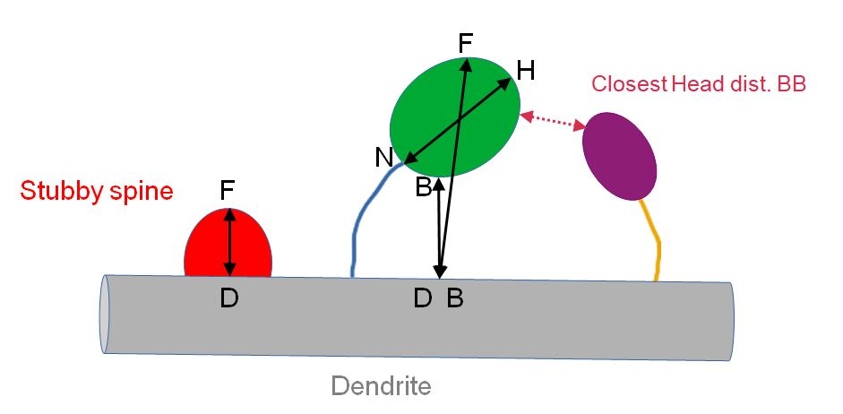
| Type | Either “Spine with neck”, or “Stubby spine”. “Stubby spine” is defined as spine for which the segmented spine head is in direct contact with the dendrite.Note that for some spines with thick neck, the segmentation process can make that the whole spine is segmented. Then the neck is made of one single voxel. In that case, the spine is classified as « Spine with neck » but the neck length=0. |
| Head Vol (Unit) | Volume of the spine head in micron cubic |
| Head Vol (pix) | Volume of the spine head in voxels |
| Neck Length (Unit) | Length of the neck in microns |
| Neck Length (pix) | Length of the neck in voxels |
| NtoH (unit) | Longest spine head diameter starting from the point of contact between the neck and the head in microns |
| NtoH (pix) | Longest spine head diameter starting from the point of contact between the neck and the head in pixels |
| Dist. BB (unit) | Border to border distance between the dendrite model and the spine head in microns |
| Dist. BB (pix) | Border to border distance between the dendrite model and the spine head in pixels |
| Dist. DF (unit) | Distance in microns between the voxel of the dendrite which is the closest to the spine head and the voxel of the spine head that is the most distant from the dendrite (Hausdorff distance) |
| Dist. DF (pix) | Distance in pixels between the voxel of the dendrite which is the closest to the spine head and the voxel of the spine head that is the most distant from the dendrite (Hausdorff distance) |
| Closest Head BB | Label of the closest spine head based on border to border distance |
| Closest Head dist. BB | Border to border distance between the spine head and the closest spine head |
| Parameter | Description |
|---|---|
| Surf (Unit) | Surface of the spine head in micron square |
| Surf (pix) | Surface of the spine head in voxels |
| SurfCorr (pix) | Corrected (smoothed) surface in voxels. More info here |
| DCMin (pix) | Smallest diameter of the spine head in pixel |
| DCMax (pix) | Longest diameter of the spine head in pixel |
| DCMean(pix) | Averge of the diameters of the spine head in pixel |
| DCMin (unit) | Smallest diameter of the spine head in pixel |
| DCMax (unit) | Longest diameter of the spine head in pixel |
| DCMean (unit) | Averge of the diameters of the spine head in pixel |
| EllVol(Unit) | Volume of the ellipse that encircles the spine head, in micron cubic |
| EllSpareness | Ratio between the volume of the ellipse and the volume of the spine head |
| EllMajRadius (Unit) | Length of the major radius of the ellipse in micron |
| EllElon | Ratio between the length of the major radius to the length of the second radius |
| EllFlateness | Ratio between the length of the second radius to and the length of the third radius. More info here |
| CX (pix), CY (pix), CZ (pix) | Geometrical centers of the spine head |
| CMx (pix), CMy (pix), CMz (pix) | Centers of mass of the spine head |
| Comp (pix) | Compactness |
| Spher (pix) | Sphericity |
| CompCorr (pix) | Compactness computed with smoothed surface |
| SpherCorr (pix) | Sphericity computed with smoothed surface. More info here |
| Min | Minimum intensity value found in the spine head |
| Max | Maximum intensity value found in the spine head |
| Mean | Mean intensity of the spine head |
| StdDev | Standard deviation for the intensity values of the spine head |
| Integrated Density | Sum of intensity values of all voxels of the spine head |
| Mode | Most frequently occurring intensity value of the spine head |
| Feret (unit) | Feret diameter of the spine head in microns |
| Feret (pxl) | Feret diameter of the spine head in pixel |
9. Analyse the colocalisation or the distance with other objects
Your image stacks may not only contain the dendrite and spines, but also another channel containing for example axonal boutons, pre or post-synaptic proteins, microglia engulfing spines… You may want to measure either their colocalisation with the segmented spine heads, or minimum 3D distance between the spine heads or necks and objects of interest.
SpotSpine retrieves an image stack with channels containing the dendrite model, the spine heads, the spine necks. Split the composite and save the segmented spine heads (or necks, or dendrite) as single channel image stack.
Segment the objects of the other channel of interest.
Open the image of segmented spine heads/necks/dendrite and open the image of segmented objects of interest.
Run the plugin DiAna to perform colocalization or distance analysis in 3D. Plugins>DiAna>DiAna_Analyse Batch process is also possible with DiAna.
Remember for Spines labeled 1, 2, 3…Spine heads are labeled 10, 20, 30…and their necks 15, 25, 35. Hence, the results obtained with colocalisation analysis can be linked with measurements given in the table obtained with SpotSpine.
The plugin Distance Analysis - DiAna is explained at this page and in the publication.
Installation
-
Download and copy the following .jar in your plugins folder Spot_Spine.jar
-
The plugin 3DImageSuite is required. Download link
-
The plugin SNT/Neuroanatomy is required. Download link
-
Both can be found in Fiji>Update…>Manager Update Sites.
-
An image stack and traced dendrite are provided for testing the plugin. Download the test image. Download the swc file of the dendrite
Citation
soon…
License
GPL distribution (see license).